wmayfield
Back to main page: Main
Project 3: Espresso Machine
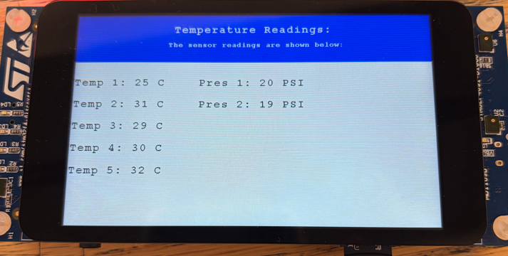
This project is for my senior design class at Colorado School of Mines. The task given to my team of 9 (2 electrical engineers, 6 mechanical engineers, 1 design engineer) was to create a new approach for an espresso machine. Initially, I was excited to create a PCB for a microcontroller to control all the mechanical peripherals, but realized this probably would take more time than was feasible for our timeline, so I opted to purchase an STM32 evaluation board. The STM32F469I-DISCO STM32 was chosen due to further requirements of a touchscreen by our client. After purchasing, I wanted to do a quick test on the board’s functionality, so I coded a display that we would use for testing temperatures throughout the machine when we got to that point for proof of concept.
Now that this thing was powered and I had proof that the MCU was going to work, I started scheming up the power distribution as my mechanical engineer teammates had started to find their parts and given me an idea of the voltage levels I would need to provide for their component choices. Initially, we had:
- A 500W boiler that took in 120VAC
- Two three way valves (Solenoids) with 12V 19W requirements
- A 24VDC Diaphragm Pump with a brushed motor requiring 24V 15.5W
- Our MCU board requiring 5V at 2.5W
- A 5V supply for a servo motor at 14W, for experimentation with tamping
Given this setup, we needed levels for 120VAC, 24VDC, 12VDC, and 5VDC.
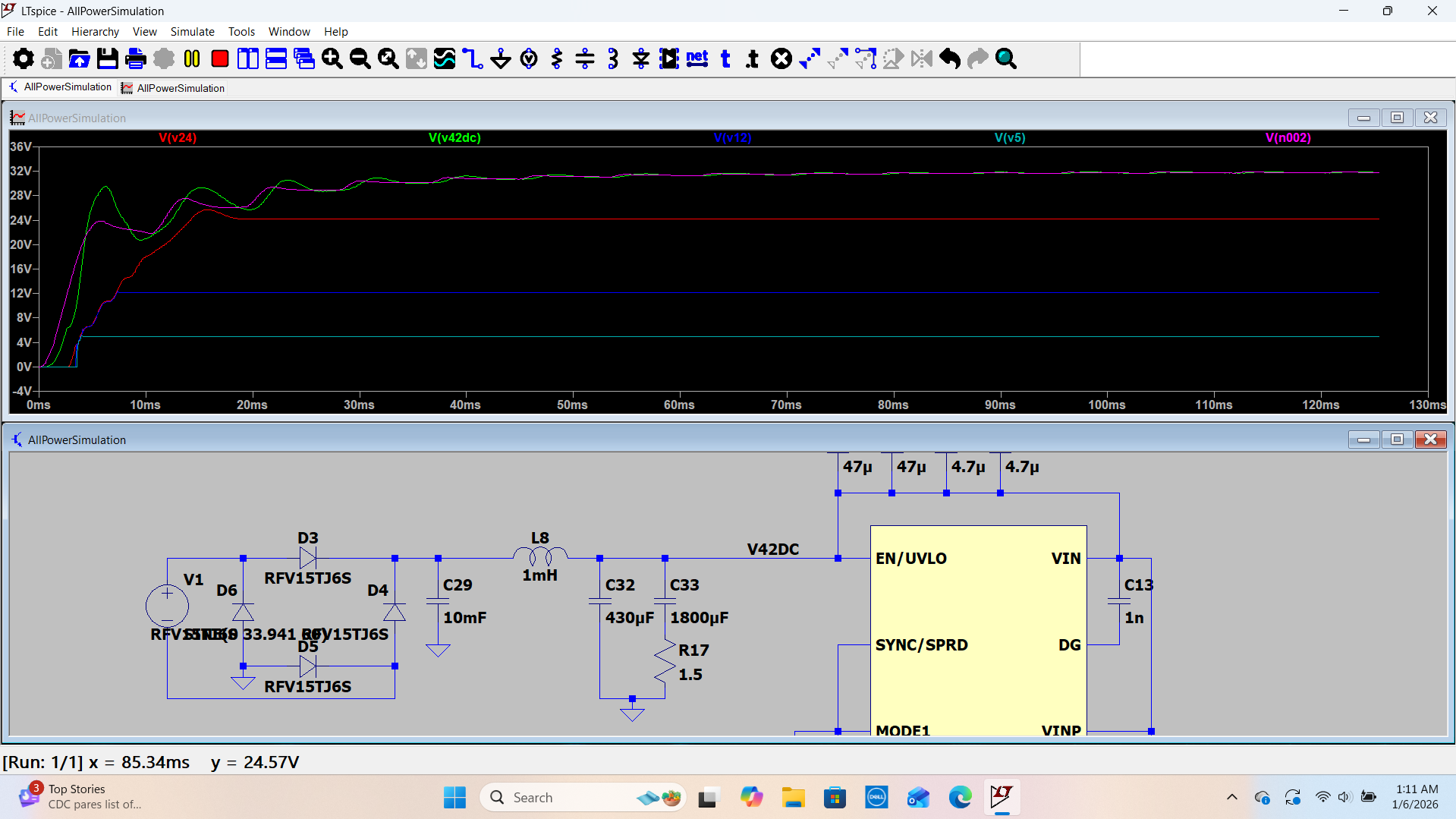
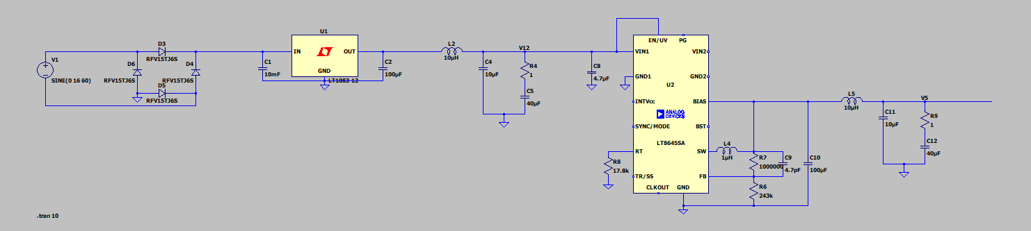
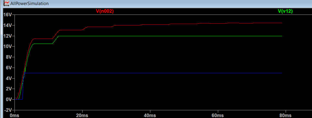
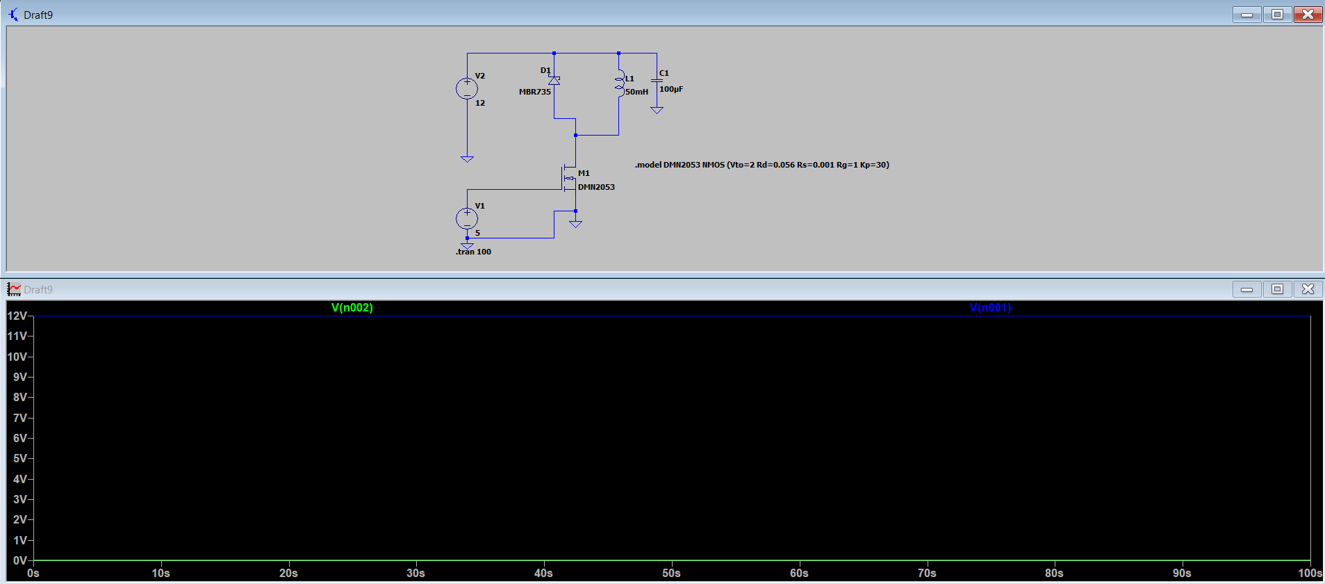
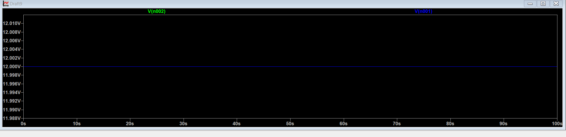
My initial approach was to have one board taking in the wall 120VAC and then providing power to a relay for the boiler, as well as providing an output for a secondary power board utilizing DC-DC converters, paralleling if necessary for power requirements. This method required me to rectify the 120VAC on my own, and for this I initially chose a full bridge rectifier, until researching and consulting reddit at which point I used an ideal diode bridge chip LT4320 for this part. Over my winter break I did some simulations on the switching converters stage, shown below. I had tried to use a beefy LC filter to eliminate the 60Hz noise and it was helpful but now I think it is overkill, however I was able to achieve some pretty clean voltage levels. The transient levels are the levels at the 10mF capacitor, as well as after the LC filter.
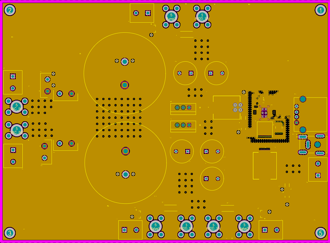
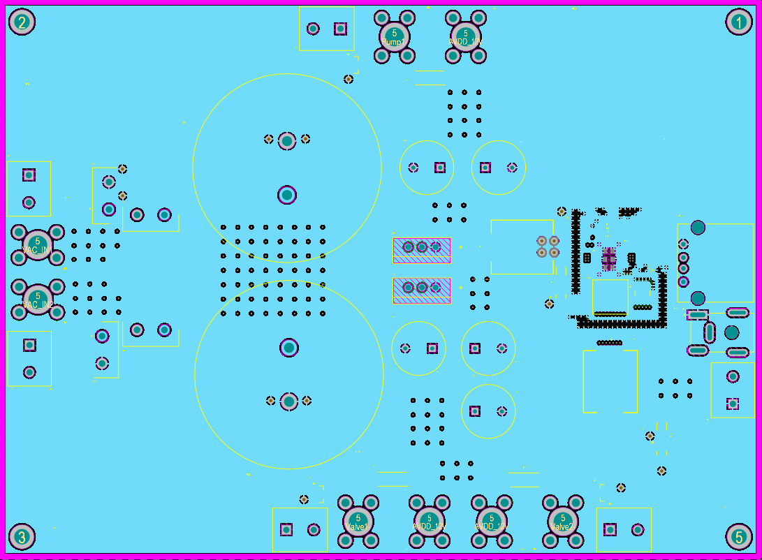
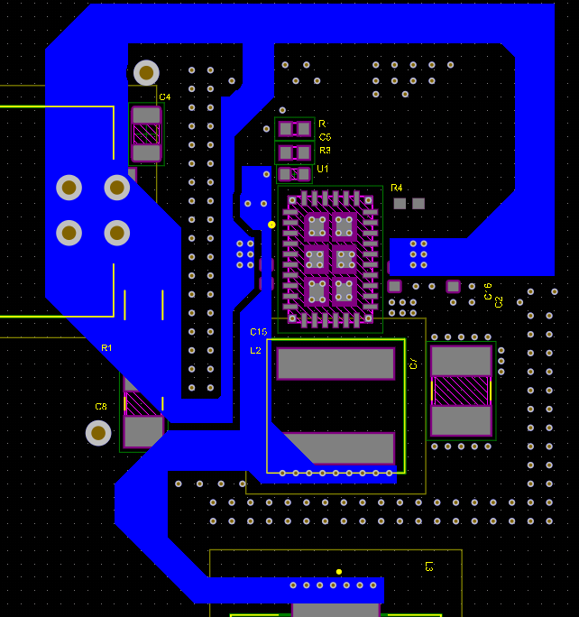
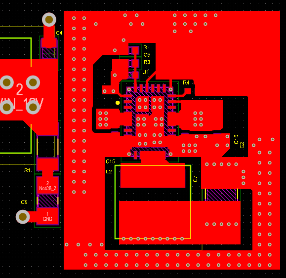
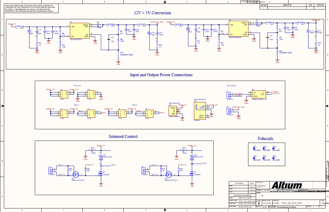
After break, new decisions were made to change the pump to a 12VDC version, so I had to change my design which will become a recurring theme in this project. But that is engineering! So, now I only needed 12VDC and 5VDC levels on this board. I was hesitant to use DC-DC converters after only rectifying now that LDOs were available, but have since learnt that this hesitation has no basis on facts and it would be fine to use a switcher after rectifying. So, I paralleled two LDOs into a 5V DC-DC converter, allowing them to also power the mechanical peripherals. I also ran a simulation on a MOSFET logic control over providing power to the solenoids after researching different methods. In hindsight, these simulations are not very telling of what happens when switching on and off, but I confirmed that this circuit would work, and then I chose a proper schottky diode for flyback, included a bypass capacitor, and chose a MOSFET based on VDS, current, and Rds. One thing to note here that I forgot about was that the MCU I chose was 3.3V GPIO, but I fix this later. I used a SIG/GND/GND/SIG stackup for power dissipation, as a good GND plane next to the first signal plane is necessary, and I needed to route on another layer which became the 4th layer.
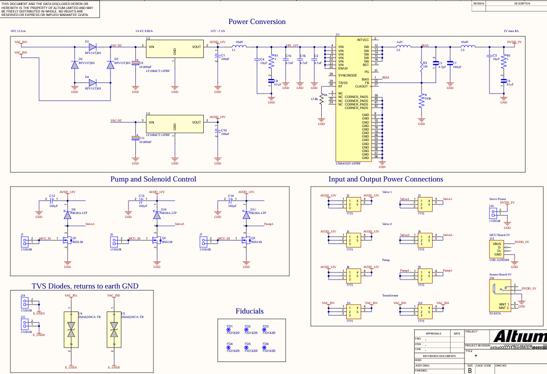
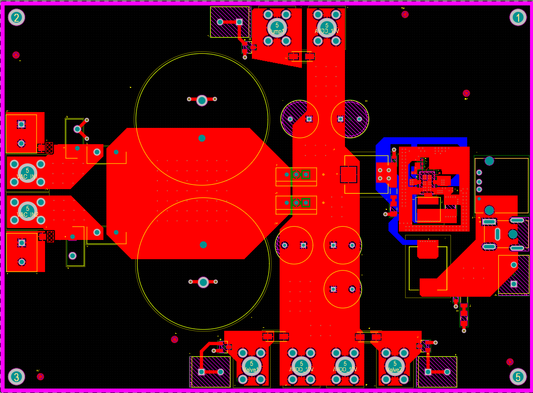
I put this schematic and layout on Reddit to receive feedback, and became more aware of better power practices like ideal converters and using switching converters on the input of the device as it will be fine to handle noisy dc inputs. Here is the link if you are interested in the feedback.
This led me to my next schematic design, and I presented my initial design work as well as my new design after receiving feedback. At this point the client told us it would be more helpful for him if we just found pre-built circuits as he did not have enough electrical engineering experience to keep replicating this and would rather just buy it.
So this was my last personal design, and then we just bought some SMPS and relays and have just been wiring up things so that the mechanical engineers in my group can test their equipment. Now I am working on the coding in the STM32 environment. When choosing these materials I just made sure that enough power was flowing from the wall into the SMPS, and that the SMPS had enough power to power each device in the worst case scenarios and it works. I also made sure the wires and enclosures could support the power levels being sent through them.
Last Updated 03/09
Back to main page: Main